HDZero Camera Expansion
Dec 26, 2025 - ⧖ 5 minThe expansion port on HDZero's goggle is commonly used for receiving an NTSC/PAL composite signal from an analogue VRX. Analogue FPV cameras output that signal too, which means you can connect a camera directly to the expansion port. Additionally the port provides 5 Volts of power. This allowed me to create an expansion module and camera bracket that all fits neatly to the left side of my goggle. Here's everything you need to know if you want to do the same!
The PCB

The PCB is shaped and sized to fit flush into the module bay. It provides power and video input on the 3-pin PicoBlade connector. The 2-pin connector interfaces to the 5-way joystick to control the camera's built-in menu. These are all tailored specifically to a Caddx Ratel 2 camera. While I've seen other cameras use similar interfaces and controls, I don't know if any other cameras will be compatible with this expansion module, although probably most Caddx cameras are. For just video and power, those should be the same on all cameras, but you might need to change connectors or adjust the pin order going into the 3-pin connector.
Preparation
As a first step, try drop the PCB into the module bay. It should drop in easily with about 0.3 mm of wiggle room around the edges. If this is not true with your module and goggle, you need to sand the module PCB down. The module should simply fall out under gravity when you tip your goggle over. If there's insufficient wiggle room, it will be difficult to remove the module once the pin header is engaged.
Module bay pin header


A 2x10 pin header with a 1.27 mm pin pitch needs to be soldered into the back of the module. Choose the best length pin header that fits your goggle. I don't know how much variance there is from one goggle to the next, so you will need to experiment.
I obtained two headers. One with a total pin length of 5.8 mm and the other 7.2 mm long. For my goggle I chose the 5.8 mm header (LCSC part C22373831). After adjusting its pins and soldering it all into place, the pin length on my module was 4.2 mm as measured in the picture on the right. If the pins are too long, the module might become difficult to remove. Potentially one could also remove unused pins to make it easier to pull the module out.
When soldering the header, use a fine soldering tip with very small amounts of solder. Inspect your work carefully with a magnifying glass or microscope. At 1.27 mm pin pitch it is very easy to inadvertently create a short circuit between pins. Here is a completed module.


Stick covers

A cute bit of aesthetic and finger comfort is a cover for the the 5-way joystick. It's a very small part so it might be difficult to print. I suggest to use an SLA printer or the finest nozzle and settings you have available.
Caddx Ratel 2 and camera bracket

I chose the Caddx Ratel 2 because it seemed to be highly regarded for video quality and low light performance. Plus it is available in red, making it a good HDZero companion.
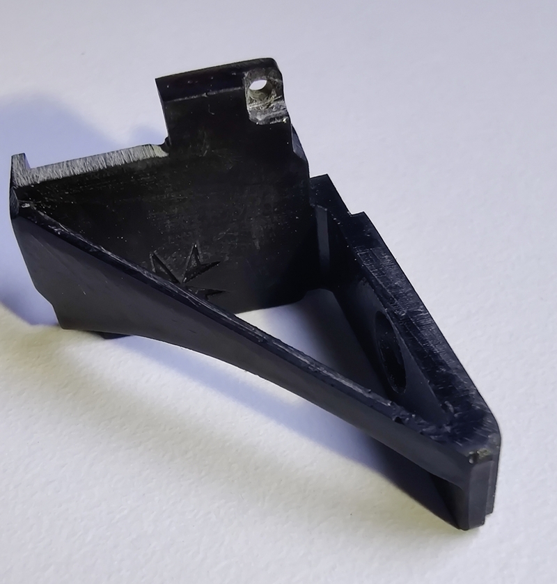
The camera bracket is designed specifically for this camera and replaces the stock Ratel 2 cover. It is a very fine print and you will have to remove some material with a knife to get it fitting perfectly.
The bracket has a counter-sink M3 screw hole for mounting it to the goggle's module bay. It self levels as you screw it down, and secures the module PCB too. Use an M3x10 mm counter-sink bolt.
Wiring

The Ratel 2 comes with all the wiring you need. In case you need to make your own, the correct pinouts are pictured to the left. Red = +5 Volts. Black = Ground. Yellow = Composite video. Green+Black = Control signal (no polarity).
Production
The STLs were printed by JLC3DP on their SLA printers, but you could print these just about anywhere, so I won't speak about the 3D printing. My PCBs were produced by JLCPCB. In theory one should be able to produce these PCBs anywhere, but JLCPCB make assembly very easy with their vast library of SMD components. Other producers might be unable to do as much of the assembly with the bill of materials that I've supplied. I can share with you the JLCPCB ordering specifics below.
Use their Standard PCB/PCBA service. Upload the gerber and choose the following options.
- Base material: FR-4
- Layers: 2
- Product type: Industrial/Consumer electronics
- Deburring: No
- Different design: 1
- Delivery format: single PCB
- PCB thickness: 1.6 mm
- PCB color: white
- Material type: FR4 TG135
- Surface finish: HASL (with lead)
- Outer copper weight: 1 oz
- Via covering: tented
- Via plating method: not specified
- Min via hole size/diameter: 0.3 mm / (0.4/0.45 mm)
- Board outline tolerance: ±0.2 mm
- Mark on PCB: Order number (specify position)
- Gold fingers, castellated holes, edge plating, blind slots, UL marking: all NO
Enable PCB assembly and select the options as below.


In the following steps, upload the Bill of Materials (BOM) and the PicknPlace (CPL) file. Eventually you should reach the following screen that displays all the top-side components with their placement.

That's about it! You'll then have some shipping options to choose from. You might need to declare a product description for Customs purposes. I think I chose "DIY HS Code 902300", but I suggest to research the best option for your situation.
The Results


 Stick Cover STL [6.8 MB]
 Schematic [49 kB]
 Pick n Place [8 kB]
 Gerber [16 kB]
 Bill of Materials [7 kB]
 Camera Bracket STL [640 kB]