Connectors Compared
Mar 15, 2026 - ⧖ 12 minHaving used BT2.0 connectors for a while now, I recently used them in a 1S toothpick build where voltage sag was quite high. Although this was mostly related to the battery cells, it got me wondering what is the actual contact resistance of BT2.0 connectors. I've seen other builders using XT30 and BT3.0 connectors for these sized quadcopters, so it seems like others are thinking along the same lines. A good reason to get some hard data on connector performance! Here are my results, with some details on the testing methodology at the end.
The lineup
There are five connector options in this size class: BetaFPV BT2.0, GNB A30, BetaFPV BT3.0, Emax EM2.0, and Amass XT30. Starting with the first two, one would assume A30 connectors are just a clever clone of BetaFPV's BT2.0, but they really are not the same connector. Therefore I have treated and tested them separately for completeness sake.

BetaFPV's BT3.0 connectors are mainly appealing to builders who will be running 2S sized packs because it includes a third pin for balancing the cells. The two primary pins are slightly larger than the BT2.0 pins, which gives BT3.0 the ability to handle higher currents and, potentially also means a lower contact resistance. Due to these larger primary pins, BT3.0 might be appealing for large 1S builds.

Emax's EM2.0 connector is quite uncommon, and despite it being open source and having some tantalising attributes, I think most hobbyists have shunned or ignored it. I can understand why, but personally this connector has intrigued me for a long time, and I wanted to get some real data on it.

Amass's XT30 is very well known and established, but uncommonly used in small quadcopters due to its weight. Being the largest and heaviest connector here, one would expect it to have the highest current rating and lowest contact resistance, which is why it is sometimes used for large 1S builds. However, there are some issues with the XT30 connector. For starters, published specifications are inconsistent. Some documents state the current rating as simply "15 A max" or "20 A max", while some state it as "15 A rated current, 30 A instantaneous current". What?
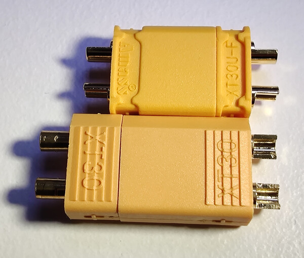
Furthermore, XT30 clones are common, and those are much heavier with unknown current specifications. For example, on the left is pictured an Amass XT30 connector with a clone below it. Perhaps there are even XT30 clones that look identically to Amass's production. To make matters worse, Amass themselves have different versions of their XT30 with very different specifications. It's hard to know what is an XT30 connector, let alone review it! For my testing I tried to obtain genuine Amass XT30 connectors of the highest standard, and hopefully that is what I received.
Connector specifications
The weights below are of a connector pair, ie. one male and one female connector. All were measured by weighing 3 connector pairs and calculating the average weight of a single pair.


| Connector | Weight (grams) | Current Rating (continuous/peak Amps) |
|---|---|---|
| BT2.0 | 0.59 | 9 / 15 |
| A30 | 0.59 | 15 / 30 |
| BT3.0 | 1.31 | 12 / 20 |
| EM2.0 | 0.92 | 10 / 20 |
| XT30 | 1.75 | 20 / 30 |
| XT30 clone | 2.2 | unknown |
It's amusing to compare GNB's A30 current rating specifications to the competition. I assume GNB exaggerated a bit.
So how much current can these connectors actually push? Regrettably I won't be testing that, and I don't know! The specifications of "peak" current are quite vague. What does "peak" mean? There's no standard definition we can lean on. It should mean that the connector can withstand that much current for a certain amount of time under certain conditions, but we have no way of knowing those specifics. Maybe the XT30 can withstand 30 Amps for 10 seconds at an ambient temperature of 30⁰ Celcius, and maybe BT2.0 can withstand 15 Amps for only 1 second at an ambient temperature of 20⁰ Celcius.
It's tempting to assume only the continuous current rating is useful, but in that case it's hard to explain the difference between BT2.0 and A30 specifications. These two connectors have identical weights and are so similar in design and materials! If both are realistic then BetaFPV must be being more conservative about their specifications than GNB are. And by extension, all the other manufacturers seem similarly as conservative as BetaFPV.
I've resigned myself to concluding that we just have to be careful and observant if we decide to push more current than the specifications suggest. I won't be put off from seeing surges of 30 Amps through BT2.0 connectors, but if I have such a quadcopter I will check for high temperatures on the connector. Connectors with the lowest contact resistance will cause the lowest power loss. Less power lost in the connector also means less heat generated in the connector, which bodes well for EM2.0 connectors after seeing its resistance measurements below.
Contact resistance test results
All resistances below are in milliohms.
| Connector | minimum | maximum | average |
|---|---|---|---|
| BT2.0 | 1.7 | 2.4 | 2.0 |
| A30 | 2.2 | 2.6 | 2.42 |
| BT3.0 | 1.5 | 1.9 | 1.63 |
| EM2.0 | 1.2 | 1.3 | 1.21 |
| XT30 | 1.8 | 1.9 | 1.83 |
Using Ohm's Law, one can calculate the power losses in Watts of each connector, at 30 Amps:
| Connector | minimum | maximum | average |
|---|---|---|---|
| BT2.0 | 1.53 | 2.16 | 1.80 |
| A30 | 1.98 | 2.34 | 2.18 |
| BT3.0 | 1.35 | 1.71 | 1.47 |
| EM2.0 | 1.08 | 1.17 | 1.09 |
| XT30 | 1.62 | 1.71 | 1.65 |
Calculator
To further my understanding on the best application of these connectors, I've written a calculator that displays the weight penalty and power gain of each connector based on my resistance measurements and on a quadcopter's weight and power specifications. The outputs are in percent relative to BT2.0 connectors. If a connector's power gain is higher than its weight penalty relative to BT2.0, then it might make a lot of sense to use that connector instead of BT2.0 connectors.
With the sample values below it appears like 1S quadcopters with an AUW of 40 grams and a max current of 30 Amps might benefit from using EM2.0 connectors. The numbers seem even better with higher currents and/or larger weights.
Cell count:
Max current: Amps
All up weight: grams
Discussion
These are the key take-aways for me:
- BT2.0 is still king due to its light weight and low resistance.
- A30 under performs relative to BT2.0 and should be avoided.
- EM2.0 offers some potential benefits for quadcopters in the 40-100 gram range.
- XT30 has a major weight penalty and should only be used where smaller connectors would burn out due to too much current. Avoid its clones!
- BT3.0 contact resistance is too high to justify its weight penalty on 1S builds, but it is very attractive for 2S builds where it will provide a substantial weight saving.
I was slightly surprised to see how poorly A30 connectors performed. They're evidently just an inferior BT2.0 knock-off. Why should anyone keep using them when BT2.0 connectors are inexpensive and widely available? I suggest to avoid them!
Seeing XT30's resistance levels was very surprising, but after thinking about it it does make sense. The extra weight of XT30 gives it the ability to carry more current without overheating, and that's about it. Although their resistance levels were very consistent, they weren't the lowest of the five connectors we tested. This connector really only makes sense on large quadcopters where you're sure you need the current capability that it offers.
What's really interesting to consider is the boundary between BT2.0, BT3.0, and EM2.0. If you're performing a custom build in the 40-100 gram AUW range and want to squeeze a bit more efficiency into your setup, I'm very inclined to suggest EM2.0 connectors. Not only do they achieve the lowest resistance levels, those levels seem very consistent over time and between different batches of connectors. Their current ratings are higher than BT2.0 and similar to BT3.0, yet they're only 0.33 grams heavier than BT2.0 and 0.39 grams lighter than BT3.0. In my experience with them, they seem like a premium product in how good they feel to use. Their contacts have just the right amount of force, they engage and disengage very smoothly and are easy to grip. They also performed the most consistently of all the connectors, measuring very repeatable resistances during my testing, which was not the case for BT2.0 and BT3.0 connectors. Of all five connectors I could easily rate EM2.0 the most premium connector, because of both their perceived material quality as well as their measured manufacturing quality.
Methodology
My milliohm measurements are made using the 4-wire Kelvin measurement technique. To the unfamiliar, this technique works as follows:
- Use a current-controlled power supply to supply a fixed amount of Amps, usually just 1 Amp, through the conductor whose resistance you want to measure.
- Use a millivolt meter to measure the voltage drop across the conductor being measured.
- Use Ohm's Law to calculate the conductor's resistance based on the fixed current and the millivolt measurement.


As a power supply I used a Sini XY-UMPD. Although it is a relatively cheap Chinese product, it seems to perform very well. To verify its current generation I used a Fluke 177 multimeter to measure current across its output. My Fluke measured 1.0 Amps when the XY-UMPD was set to a constant current output of 0.993 Amps, and this reading was stable over time to less than 5 mA (0.5 %). I subsequently used the 0.993 Amps setting for all of my 4-wire testing.
I used new, unused connector pairs for all the connectors I tested. I assembled them with wiring soldered to the male connector, and a shorted bridge soldered across the female connector. All the wiring used came from the same spools of 22 AWG, and all wires were cut to the same lengths for all of the assemblies. Each connector type had 3 assemblies, which gave me the ability to record 3 independent measurements for each connector type. With the exception of the BT3.0 connectors, which only had 2 assemblies (sorry, I didn't have enough BT3.0 connectors to build 3 assemblies).

Furthermore, I spread my testing over time by measuring every assembly 3 times. Each measuring event was separated by 1-3 weeks of time. At the start of each measuring event, every assembly had their connector pairs disengaged and then re-engaged before testing them. In total I recorded 9 measurements for each connector type (3 assemblies tested 3 times over many weeks). Again with the exception of BT3.0 connectors which only saw 6 measurements due to me having only 2 assemblies of them.
During the course of testing I noticed that some connectors were less consistent than others. BT2.0, BT3.0, and A30 connectors were all sensitive to physical movement on the connector. I did my best to measure these connectors as beneficially as I could by trying to achieve the lowest easily repeatable resistance figures amongst the inconsistent performance. These inconsistencies are reflected in the data by minimum, maximum, and average resistance values. In real world use of these connectors one will not be able to tell if their connection is optimal, so it's something to keep in mind when comparing to connectors like EM2.0 and XT30 which both performed more consistently.
Finally, for the calculator, I just loaded my milliohm and weight measurements of all the connectors into code. It uses Ohm's law to calculate the power losses of each connector type, and then basic arithmetic to calculate the power gain and weight penalty percentage relative to BT2.0 connectors. The JavaScript source code is easily viewable in the source code of this page.